ZGR-2 is a product that allows wireless remote-control of NIKON cameras by smartphone. Its functions include sending GPS information from smartphones to Nikon digital cameras, recording location data in EXIF photo information while taking a photograph, long-time exposure, setting continuous multiple shoots, long-distance remote-control shoots, taking a photograph by shaking the smartphone, as well as controlling multiple cameras with one smart phone, etc.
SmartShutter is a product that allows wireless remote-control of CANON, OLYMPUS, SONY, and PENTAX cameras with a smartphone. Its functions include long-time exposure, setting continuous multiple shoots, long-distance remote-control shoots, taking photographs by shaking the smartphone, as well as controlling multiple cameras with one smartphone, etc.
For the SmartShutter accessory without the GPS recording function, smartphone software provides the function of GPS tracking which helps users integrate GPS data into EXIF photo information during post-processing.
After set shooting begins, exiting the application on the smartphone will not affect continuous recording of GPS data. This product has low power consumption which ensures that it will last through long photo sessions.
In addition, this product can be used as a manual release cable which provides more stability, convenience and reliability during photography.
Remote-control photography allows for easier shoots when quick reactions are important, such as when photographing animals, extreme situations, or field surveying.
Product Composition
This product has two components: the camera accessory and the smartphone app.
1. Accessories
² ZGR-2a, ZGR-2b, SS-C1,SS-C2,SS-O1,SS-S1
2. Software
Smartphone application SmartShutter (Free download)
² FOR iPhone series users, please download SmartShutter Application(free) at AppleStore
² For Android series users, please refer to the latest information on our Homepage:
Accessory Description and Camera Models
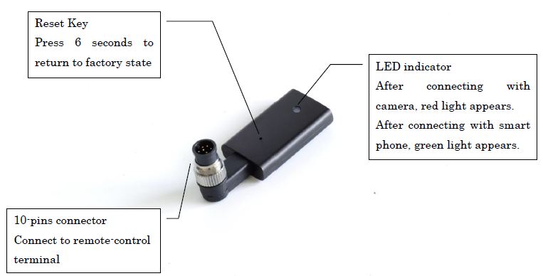
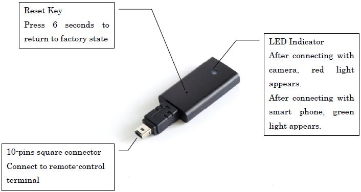
ZGR-2
Description
ZGR-2a has a 10-pin connector shown as follows
ZGR-2b has a 10-pin connector shown as follows:
Camera models
This product includes both ZGR-2a and ZGR-2b. Please confirm your digital camera models before purchase.
| Description | Camera Models |
| ZGR-2a | |
| ZGR-2b |
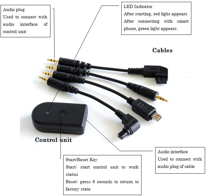
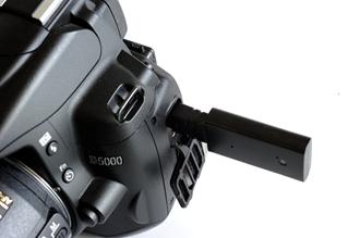
SmartShutter
Accessory description
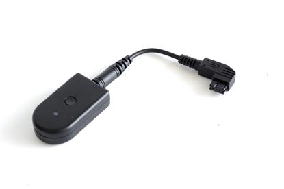
The SmartShutter Accessory is composed of a control unit and a cable. Please confirm your camera model and interface before purchase. The following figure shows the control unit and cables.
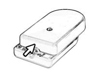
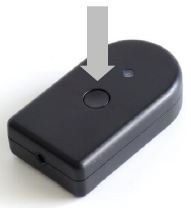
How to install and remove the control unit battery.
The CR2032 button battery is installed in the control unit. Open the box from the back to change the battery.
Step1. Remove the screws
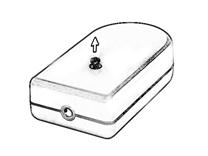
Step2. Push the cover horizontally, following the direction of the arrow. (Never pull open the cover directly.)
Step3. Change the CR2032 button battery. (Hold the base while removing the battery.)
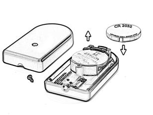
Step4. Push the cover horizontally, following the direction of the arrow.
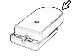
Step5. Replace the screw. (Be careful not to push too hard, so as not to damage the screw’s thread.)

Accessory Assembly
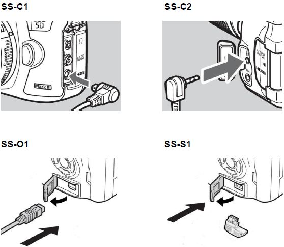
Connect The Audio plug cable to the audio interface of the control unit and the other end to the remote-control interface of the camera as follows. (For example see SS-S1)
Camera Models
The four products displayed here correspond to the following digital models in this figure. Please confirm the manufacturer and model of your camera before purchase.
| Description | Camera Models |
| SS-C1 | |
| SS-C2 | |
| SS-O1 | |
| SS-S1 |
Smart Phone Models
iPhone 4S/5,iPod 5,iPad 3/4/mini
iOS 5.1 or later
Android Smart Phone: Because the Android smartphone has many complex and diverse versions, please refer to the latest information on our homepage.
http://www.zesty.co.jp/
Connect ZGR-2 to camera
Step 1. Power off the camera
Be sure to power off the camera before connecting to avoid malfunction.
Step 2. Connect to the camera’s remote-control interface
Connect ZGR-2a round connector to the corresponding interface of the camera as shown and tighten the fixing.
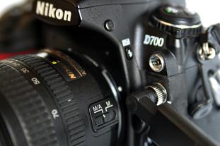
Connect ZGR-2b square connector and confirm as shown.
Connect SmartShutter to camera
Step 1. Power off the camera
Be sure to power off the camera before connecting to avoid malfunction.
Step 2. Connect to the camera’s remote-control interface
Connect to the corresponding interface of the camera as shown.
Press the button on the control unit to start
Attention: In order to extend the battery life, the control unit will automatically enter into an idle state when not in use. Press the button on the control unit to reconnect with your smartphone when you need to use it again.
Quick start
Step 1. Power on the camera
Step 2. Check to make sure the smartphone software is installed
If the application is not installed on your smartphone, download as follows:
² For iPhone users: Download the SmartShutter application from the Apple Store for free
² For Android users: Please refer to the latest information on our homepage.
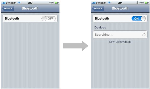
Step 3. Set Bluetooth before starting the application
The products cannot work without activating Bluetooth. For iPhone users, start Bluetooth as follows.
Step 4. Start the application
Start the SmartShutter application. The following screen will appear. See an example of the ZGR-2a model below.
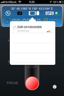
The Smartphone will begin to connect automatically with ZGR-2. when the connection is made, the following screen will appear.

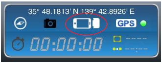
Once the product icon in the following figure stops flashing, the connection is successful. You can now use the software to control your camera.
Step 5. Shooting
Press the product icon. When the following mark appears, the connection is good, and the signal is strong. You can now take pictures.
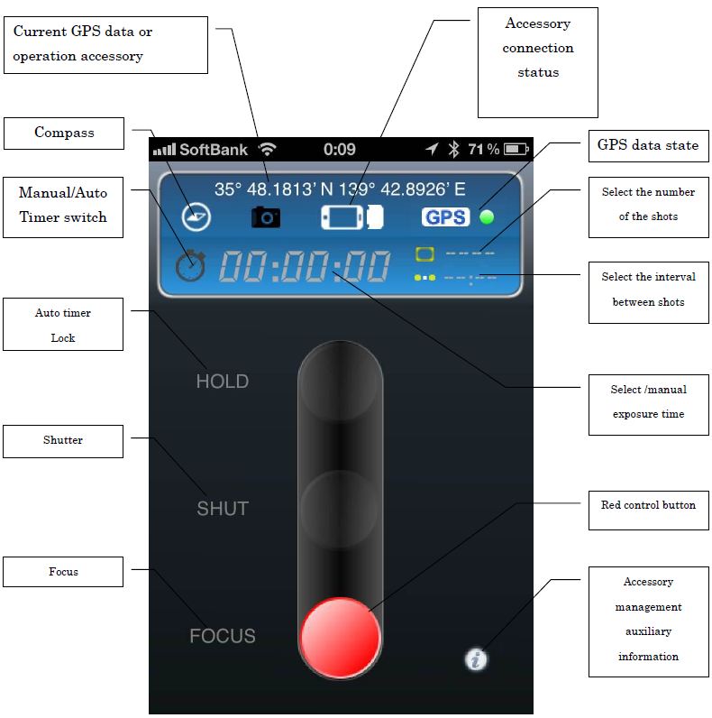
Main operation interface
Description of the functions in the main operation interface
Popup Menu Description of Main Interface
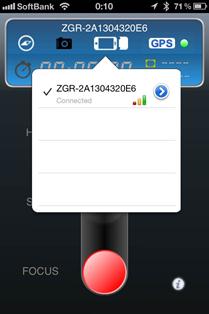
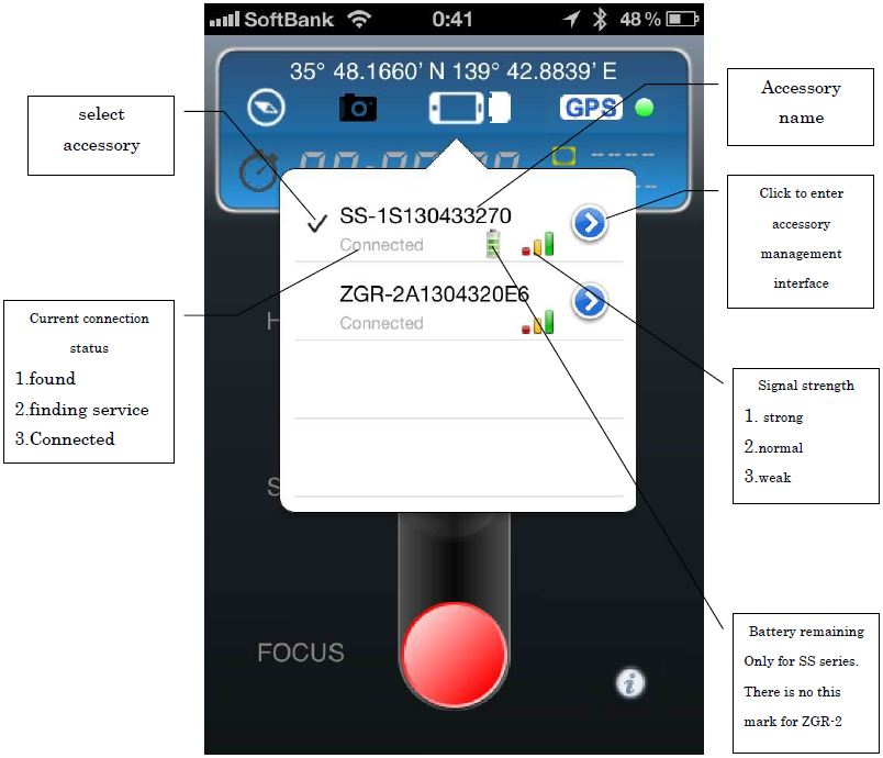
Press the product connecting status icon to display the following accessories list.
Timer Controller Setting
This application supports Automatic Timer Mode and Manual Mode.
The Automatic Timer Mode includes exposure time, interval time, and delay time set up functions. Manual mode provides a remote shutter release function.
Automatic Timer Mode
Step1 Camera Setting
For using the long-exposure time function, Nikon DSLR cameras MUST be set as following:
| Exposure Mode | Manual |
| Shutter Speed | BULB |
To use the interval time function, Nikon DSLR cameras MUST be set as following.
| Interval Timer | OFF |
Certainly, both functions above can be used simultaneously.
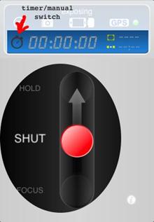
Step2 Mode Switch
Press the icon shown below, following the direction of the arrow, to enable the exposure time set function
Step3 Set Exposure Time
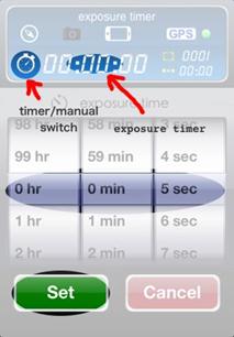
When the exposure time is set to 00:00:00, the camera shutter speed is controlled by the camera itself
Step4 Set the number number of shots, interval time, and delay time
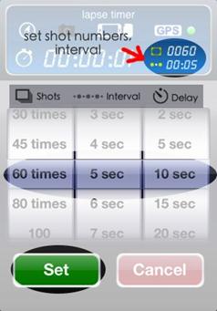
Step5 Take Photos
Push the red button or use the iPhone’s volume button to control focus, shut and hold status.
Features:
Exposure time: 0s to 99hrs 59min 59s in one-second increments
Interval: 1s to 90min in couple second increments
Delay Start: 0s to 90min in couple second increments
Number of shots: 1 to 6000
Manual Mode
You can switch the timer into manual mode, and adjust the focus mode of the camera lens.
| Focus Mode | Auto Focus or Manual |
Press the red button or use the iPhone’s volume button to control focus, shut and hold status.
GPS Function
Since the ACCESSORY obtains GPS and map information from the Smartphone, it is as accurate as the smartphone it is connected to.
Smartphones use A-GPS (“Assisted GPS”) which, in basic terms, accesses an intermediary server when it is not possible to connect directly to a satellite -- indoors, for example -- and this server provides the nearest satellite with additional information to more accurately determine the users’ position.
Smartphones also use Wi-Fi hotspots and cellular towers to get the most accurate location quickly when GPS is not the most convenient method of location detection. Sometimes a smartphone is somewhere otherwise inaccessible to GPS, such as in the ocean, on a mountain, or underground. In these cases, you can get a more accurate position by adjusting your GPS position manually.
Step1 Confirm the Smartphone GPS Function
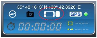
When the GPS icon turns green, GPS data is being sent to the camera.
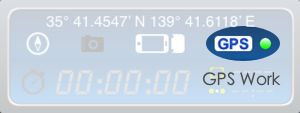
When the GPS icon turns red , GPS is not working correctly or is disabled. Open [Settings], open [Location Services], and enable the [ZGR-1 Nikon] application.
When the GPS icon turns gray , the GPS transfer function is disabled by the application. Press the GPS icon to enable the GPS transfer function.
If the icon is yellow, the smartphone is searching for GPS data. Please wait, or check the GPS settings of your phone.
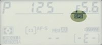
Step2 Confirm the GPS on your camera
For NIKON users, a GPS icon will be displayed in the control panel on the top of the camera.
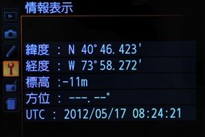
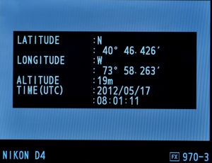
Step3 Confirm GPS data in your Camera
To view GPS data, select GPS → Position in the camera setup menu. (This option is not available with the D2X, D2XS, D2HS, and D200 cameras.) The current latitude, longitude, altitude, and Coordinated Universal Time (UTC) will be displayed as following.
Step 4. Confirm GPS Data in your Photos.
Extended Functions
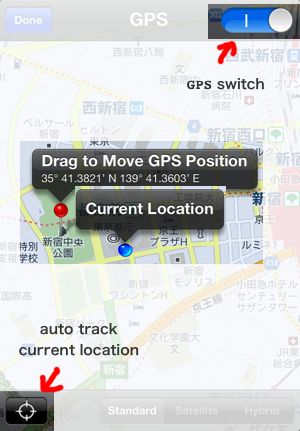
Press  for GPS settings, and use the top right switch to enable/disable GPS function. The blue point shows your current location, and the red pin shows the GPS location. By default, the red pin tracks your current location. You can move it to a new location for your photographs
Setting accessory names and connecting to multiple accessories
For ease of use, accessory names may be changed. Multiple ZGR-2 and SmartShutter accessories may be connected. Settings may be set as shown.
To change accessory name
Press the accessory icon
The accessory list will appear, press the blue arrow button.
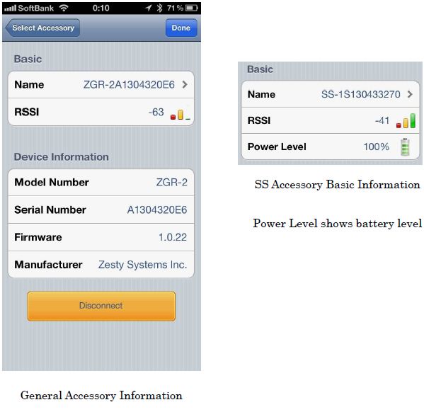
As shown below, detailed information on the current accessory (including name, signal strength, model number, serial number, firmware, manufacture, etc.) will be displayed. SS series accessories will also display their remaining battery life. Press the arrow to the right of the name of an accessory to change its name.
As shown type into the name text input box your desired name. (At most 15 characters.)
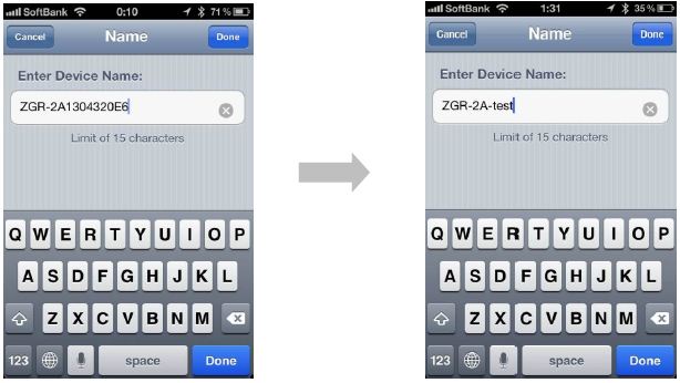
Once the name has been typed in, press DONE on the top right corner to return to the main screen of the app. Press the accessory icon to confirm .
Multiple accessory connection
SmartShutter Application supports the control of one smart phone to multiple ZGR-2 and SmartShutter accessories. If you have multiple cameras, you can connect ZGR-2 and SmartShutter to each of them and control them with one smart phone.
The following is an example of how to connect to two cameras
When a second accessory is connected to a camera, the following will be displayed on the main interface screen (left.) Click SS-1S139433270 accessory to connect (right.) The Smartphone may now control multiple cameras.
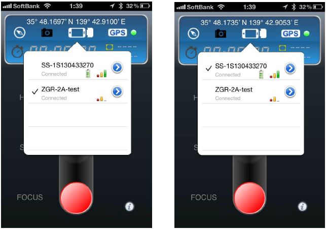
You can select an accessory by lightly tapping the left part of the accessory name. All operations will be transmitted to the selected accessory.
Note: This product supports the selection and control of five accessories.
Management of Auxiliary information settings
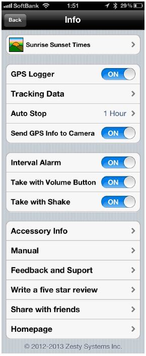
This product is designed for photographers. To facilitate better photography, beyond GPS and timing operation functions, this product can also supply position and time information. Auxiliary information includes compass, sunrise and suset times, GPS logging, tracking data, etc.
Accessory management includes auto stop, internal alarm, picture taking with the volume button or with a phone shake, etc.
This product also provides accessory information, a manual, as well as feedback and support at our website. If you can, please write a five star review and share information on this product with your friends.
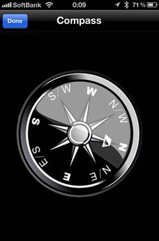
.Compass
Press COMPASS on the upper left corner of the main application screen to enter into the following screen. Turn the phone horizontally to confirm the compass directions. (E, W, S, N, N/E, N/W, E/S, S/W.).
.Accessory management and auxiliary information
Lightly tap on the lower right corner of the main interface screen to enter into accessory management and the auxiliary information screen.
.Sunrise and sunset
Click the right arrow next to SUNRISE AND SUNSET to enter the SUNRISE AND SUNSET screen. The following figure shows the sunrise and sunset information of your current position (automatically calculated based on GPS position and time data.)
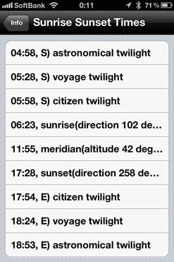
Terminology
Astronomical twilight:
The time when the center of the sun is between 12° and 18° below the horizon
Voyage twilight
The time when the center of the sun is between 6° and 12° below the horizon
Citizen twilight
The time when the geometric center of the sun is 6° below the horizon
Sunrise
The instant at which the upper edge of the Sun appears on the horizon
Meridian
An imaginary arc on the Earth's surface from the North Pole to the South Pole
Sunset
The daily disappearance of the Sun below the western half of the horizon
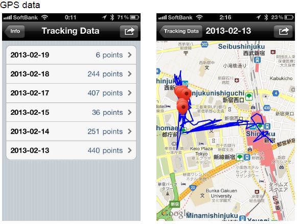
. GPS Logger and tracking data
This smartphone application provides a GPS track recording function.
This function can work independently of the camera. Tracking smartphone data can be automatically recorded adn stored in the smartphone. The saved data can e recorded into photo data by special software during post-processing. ZGR-2 and SmartShutter users can use this function to process the position information of pictures.
.Method of merging GPS data into EXIF in post-processing
Step 1. Get GPS data
Lightly tap the word SENDING on the upper right corner of the uper left figure to open teh figure below.
This application saves standard gpx data file for post-processing. Users can send the gps data saved in the smartphone through the following options.
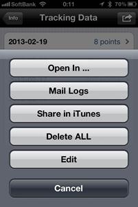
Open in
Get gpx data through Dropbox in smart phone
Mail logs
Send gpx data to the designated mail address
Share in iTunes
Get gpx data through iTunes
Delete all
Delete all GPS information
edit
Edit and delete GPS information
Step 2. Add GPS information to photo EXIF through software
Many free software programs are designed to merge gpx data with photos, such as NIKON viewNX2. For details, please refer to the instructions of those software programs.
.Automatically stop GPS
In order to reduce the considerable power consumption caused by the GPS function, this application allows you to control how long after the app begins to run in background mode to continue transmitting GPS data.
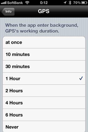
Users can select a time in the figure above to stop sending GPS information to the ZGR-2. After the above time limit is reached, the smartphone will automatically stop sending GPS information, even if the smartphone is not currently being used.
.Send information to camera
.Interval Alarm
Starts or stops warning tone. If selected, a three beat tone plays before exposure.
.Take with volume button
For convenient shooting, the volume button on the side of the smartphone can be used to lock and unlock shooting. The Volume up button may be set to lock status, which will put the ap’s red button in lock position. The volume down button will unlock shooting status, which will push the apps’ red button into focus position.
.Take with shake
For convenient shooting, this option allows you to shake your smartphone to trigger the shutter. If this option is selected, shaking the smartphone while the app is at the main interface screen will have the same effect as pressing the shutter button.
.Accessory information
This option displays accessory information and allows you change accessory names. Please refer to an earlier section of the manual to change an accessory’s name.
.Manual
Displays the accessory opeartion manual
.Feedback and support
Send email to the support center, and feedback advice
.Write a reviewく
Enters into iTunes to give a review
.Share with friends
Share with friends through email, Twitter, Facebook, Vkontaket, LinkedIn, etc. Visit the ZestySystems homepage to read the latest product information.
Homepage
Visit ZestySystems HP to check the latest product information
Specification
| Name | Wireless GPS Unit and Timer Remote Controller | Wireless Timer Remote Controller and GPS Logger | ||||
| No | ZGR-2a | ZGR-2b | SS-C1 | SS-C1 | SS-O1 | SS-S1 |
| Jan Code | 4562343221031 | 4562343221048 | 4562343221123 | 4562343221116 | 4562343221154 | 4562343221161 |
| Interface | 10pin Round Connector | 10pin Square Socket | N3 Type | E3 Type | Multi-USB Connector | Sony |
| Power Consumption | Approx. 10mW | Approx. 3mW | ||||
| Size | 58(H)x20(W)x23(D) | 61(H)x20(W)x8(D)mm | Control Unit:45(H)x26(W)x11(D)mm Cable:Approx. 11mm~13mm | |||
| Weight | Approx. 20g | Approx. 20g | Approx. 25g | |||
| Environment | Temp: 0 °C – 40 °C/32 °F – 104 °F. Humidtiy : 20% - 80% | |||||
| Package Size | 135(H)×70(W)×28(D)mm | 135(H)×70(W)×20(D)mm | 135(H)×70(W)×20(D)mm | |||
| Package Weight | Approx. 40g | Approx. 40g | Approx. 50g | |||
| Certification/Directive | TELEC, CE, RoHS | |||||